We use cookies to provide you with the best possible experience. They also allow us to analyze user behavior in order to constantly improve the website for you. Find out more.
Necessary
Analytics
Preferences
Marketing
We're exhibiting at LAMMA 2025, find us at stand 6.644
Custom cable design UK: A wire-to-board connector selection guide for OEM engineers
Custom cable design UK advice for OEM engineers, covering connectors, crimping, sealing and prototyping with an OEM cable assembly manufacturer UK.
For OEM teams seeking custom cable design UK support, connector choice is one of the earliest decisions that can create problems later. A connector that appears suitable on a drawing may prove difficult to assemble, carry less current than expected, work with the wrong cable gauge or become unreliable after repeated mating. By the time that problem appears during prototyping, testing or production, changing it may also mean revising the PCB, cable assembly, tooling and documentation.
Choosing the right connector from the outset helps improve reliability, manufacturability and long-term product performance.
The connector itself may represent only a small part of the component cost. For an OEM, however, cable rework costs can extend into engineering time, delayed builds, replacement parts and repeat testing.
This guide focuses specifically on wire-to-board connector selection and the practical details that should be considered when preparing an OEM cable assembly specification.
What is a wire-to-board connector?
A wire-to-board connector creates a removable or permanent electrical connection between individual wires or a cable assembly and a printed circuit board.
The cable side will usually contain terminated wires held within a connector housing, while the PCB carries the corresponding header or receptacle. Depending on the system, the connection may carry power, signals, data or a combination of these.
Wire-to-board connectors are available in a wide range of sizes, configurations and locking mechanisms to suit different applications.
Wire-to-board connector families range from compact, fine-pitch products for space-constrained electronics to larger power connectors capable of carrying higher currents. Locking options can include friction locks, full locks and secondary retention devices designed to help keep terminals seated correctly.
The correct choice therefore depends on the complete application, not simply the number of circuits required.
Wire-to-board connector selection guide
A useful wire-to-board connector selection guide should begin with the operating conditions and electrical requirements, then work back towards the physical connector.
Pitch size and available space
Connector pitch is the centre-to-centre spacing between adjacent contacts.
A smaller pitch can reduce the PCB footprint and help fit more circuits into a restricted space. However, compact size should not be considered in isolation. The design must still allow room for the housing, latch, cable exit, bend radius and any tooling or hand access needed during assembly.
Pitch also influences the connector families, contact sizes and current capacities available. Commercial wire-to-board ranges span everything from very fine-pitch signal connectors to larger power products, with electrical performance varying significantly between families.
Design engineers should check:
PCB footprint and component clearance
Connector height and orientation
Number of circuits
Cable exit direction
Access for mating and release
Space for strain relief and routing
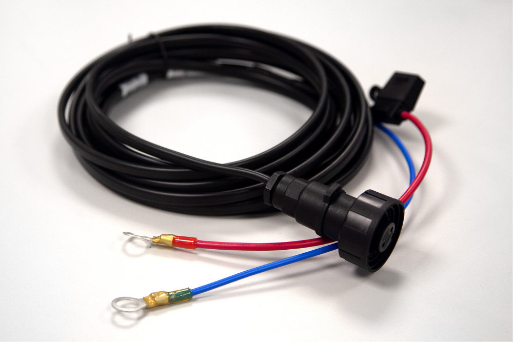
A connector may fit the board perfectly while leaving too little room to install or service the finished cable. Where heatshrink forms part of the design, the specification should define its material, diameter, finished length and purpose, such as insulation, sealing, identification or strain relief.
Considering manufacturing requirements early helps ensure connector specifications can be produced consistently from prototype through to production.
Current rating and wire gauge
The connector must carry the expected electrical load without exceeding the limits of its contacts, housing, PCB interface or cable.
Current ratings are not always a single fixed figure. They may depend on wire size, ambient temperature, contact material, the number of circuits carrying current simultaneously and the PCB trace design. Manufacturer data may also include derating information rather than one universal operating value.
The terminal must also be approved for the selected conductor size and insulation diameter. Using an undersized conductor for the electrical load, or attempting to crimp a terminal onto a wire outside its specified range, can compromise both mechanical retention and electrical performance.
The OEM cable assembly specification should therefore state the conductor size, insulation type, maximum current, voltage and expected duty cycle rather than relying on the connector series name alone.
Operating temperature
Temperature selection should account for both the external environment and the heat generated by current flowing through the connection.
The rated temperature of the connector housing, contacts, cable insulation and nearby PCB components all need to suit the application. In enclosed equipment, the local temperature around the connector may be higher than the general ambient temperature outside the unit.
Connector specifications can vary considerably. Some families are designed for typical commercial environments, while others operate across much wider temperature ranges. The cable rating also needs to be considered alongside the connector rating.
Environmental sealing and IP ratings
Equipment used outdoors, around washdown processes or in dusty industrial environments may require a sealed connector system.
IP ratings are defined under IEC 60529 and describe protection against the intrusion of solids and liquids. The rating should be considered for the connector in its intended state, which may mean fully mated and fitted with the specified seals, backshells or blanking plugs.
For UK OEMs specifying IP67 or IP68 sealed cable assemblies, it is important to check:
Whether the rating applies when the connector is mated
Which cable diameter and seals are required
Whether unused cavities need blanking
The immersion or exposure conditions covered
How the complete assembly will be tested
An IP-rated connector does not automatically make the whole cable assembly suitable for every wet or contaminated environment. The cable entry, terminations, joints and any overmoulded or heat-shrunk areas also need to support the required level of protection.
Sealed wire-to-board products are available for harsh and space-constrained applications, including connector families designed to provide IP67 protection when correctly assembled.
Selecting suitable connectors, seals and cable protection helps assemblies perform reliably in demanding operating environments.
Locking and terminal retention
A simple friction lock may be sufficient inside protected equipment that remains stationary and is rarely opened.
Applications involving vibration, movement or regular handling may need a positive latch, screw fixing or additional retention features. Terminal Position Assurance and Connector Position Assurance devices can also help confirm that terminals are fully seated and connectors remain properly mated.
Designers should consider:
Expected vibration and shock
Pull forces on the cable
Whether the connection is accessible in service
The risk of accidental release
Whether operators can confirm correct mating
How easily the connector must be disconnected
The most secure locking method is not automatically the best. A connector that cannot be released safely or reached during maintenance can create a different set of problems.
Common connector specification mistakes
Several avoidable issues regularly emerge when an assembly moves from CAD into a physical build.
Underrating the connection
Choosing a connector too close to the expected maximum load leaves little allowance for temperature, simultaneous circuit loading or future system changes. Ratings should be checked against the manufacturer’s test conditions and derating information.
Ignoring mating cycles
Not every connector is intended for frequent disconnection.
Product durability can vary from only a small number of mating cycles to hundreds, depending on the contact design, plating and connector family. A connection used during routine servicing may therefore need a different specification from one mated once during final assembly.
Mismatching terminals and cable gauge
A housing may accept several terminal variants, but each terminal will have a defined conductor and insulation range. The contact, wire and tooling need to be treated as a matched system.
Overlooking assembly access
A connector that fits into the product model may still be difficult to crimp, populate, latch or disconnect. Cable routing and assembly order should be reviewed alongside the PCB layout.
Specifying a connector without checking availability
Selecting an unusual component without reviewing lead times, minimum order quantities or approved alternatives can create supply problems later. Early manufacturer involvement allows sourcing risk to be considered before the design is released.
Crimping vs soldering cable connectors
There is no single termination method that is right for every assembly.
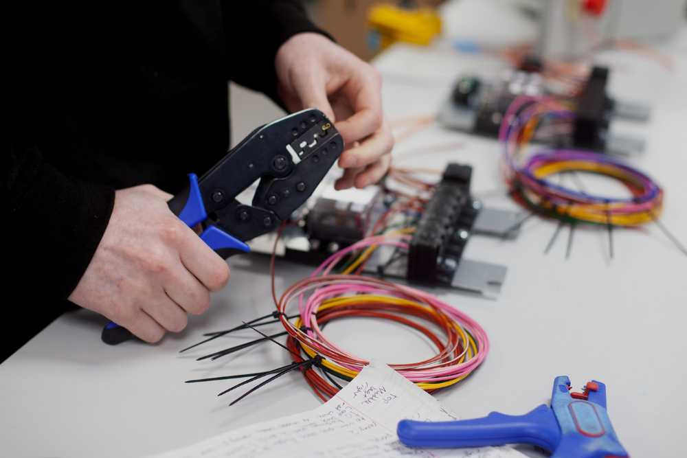
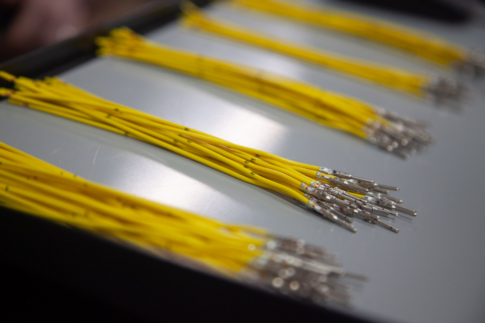
Crimping creates a mechanical and electrical connection by compressing a specified terminal around the conductor using matched tooling. When the terminal, wire, crimp height and tooling are correctly controlled, it supports repeatable production without introducing solder, heat or flux.
Whether using crimped or soldered terminations, controlled manufacturing processes help deliver consistent electrical and mechanical performance.
Soldered terminations remain appropriate for connector styles and applications designed around them, including certain PCB, shield and specialist connections. They require their own process controls, inspection criteria and strain-relief considerations. IPC/WHMA-A-620 recognises both crimped and soldered interconnections within cable and wire harness manufacture.
When comparing crimping vs soldering cable connectors, the decision should be based on:
The connector manufacturer’s specification
Production quantity
Service environment
Vibration and movement
Inspection requirements
Available tooling and process controls
Whether the connection needs future repair or modification
An established off-the-shelf connector is often the sensible choice where:
Electrical loads are comfortably within its ratings
The operating environment is straightforward
Space and orientation are already resolved
The connector is readily available
Standard tooling and contacts can be used
The application does not need unusual sealing or retention
Custom does not need to mean inventing a new connector. In many projects, custom cable design UK support involves selecting and configuring proven components around the exact cable length, routing, labelling and equipment interface.
When should the cable assembly manufacturer be involved?
Manufacturer input becomes more valuable when the assembly involves restricted space, high current, environmental sealing, unusual cable materials, repeated mating or a transition from prototype into volume production.
Early manufacturer involvement can identify design, routing and production considerations before a project moves into full-scale manufacture.
Early review can help identify whether:
The selected terminal matches the wire
Suitable production tooling exists
The connector can be assembled and inspected reliably
Components are readily available
Sealing requirements are achievable
The design can be reproduced efficiently
Test access and acceptance criteria are clear
This is particularly useful for low-volume cable assembly prototyping in the UK, where an early physical build can reveal routing, access and connector-orientation issues before the design is frozen.
A bespoke cable assembly short run also gives engineering teams the opportunity to validate fit and function before committing to repeat production.
Looking for a high performance wiring provider? Discuss your cable design requirements with Tec-Stop
Tec-Stop designs and manufactures custom cable assemblies from its Worcester facility, supporting both small-batch prototyping and repeat production. Its published capabilities include simple wiring assemblies, complex multi-core cables with custom connectors, strip and crimp termination, soldering, testing and ISO 9001-controlled production.
Tec-Stop is an OEM cable assembly manufacturer UK customers can involve from the specification and prototype stages through to ongoing production supply.
From connector selection and prototyping to repeat production, Tec-Stop manufactures bespoke cable assemblies for OEM customers across the UK and beyond.
Speak to our friendly, knowledgeable team about your connector selection, cable routing, termination, testing and production requirements.
Custom cable assemblies designed and manufactured in Worcester, with products supplied across the UK, Europe and internationally.
A connector can look right on a drawing but still cause problems when you come to build the assembly. Getting us involved early means we can look at the wire, terminals, tooling, routing and assembly access before the design is frozen.
What should be included in a custom cable design UK specification?
A custom cable design UK specification should define the electrical load, conductor size, connector type, cable length, operating temperature, environmental exposure, routing constraints and testing requirements. It should also record expected mating cycles, bend radius, labelling, shielding and production quantities so the manufacturer can assess whether the proposed design is practical and repeatable.
What does an OEM cable assembly manufacturer UK need before production begins?
An OEM cable assembly manufacturer UK normally needs approved drawings, a bill of materials, connector and terminal details, wire specifications, acceptance criteria and anticipated production volumes. Sharing these requirements early allows the manufacturer to review component compatibility, tooling, assembly access and quality controls before the custom cable enters production.
When do OEMs need custom cable solutions rather than standard cables?
OEMs need custom cable solutions when standard products cannot meet the required length, connector configuration, routing, electrical performance or operating environment. A custom assembly may also be appropriate where equipment requires specialist labelling, shielding, environmental sealing or integration with an existing board, enclosure or control system.
How do I select a wire-to-board connector for a custom cable assembly?
A wire-to-board connector for a custom cable assembly should be selected according to pitch, current and voltage ratings, conductor range, temperature limits, locking method and environmental requirements. Engineers should also check PCB clearance, cable exit direction, mating access and whether the chosen terminal can be crimped consistently onto the specified wire gauge.
Can custom cable assemblies be designed for high-performance environments?
Yes, custom cable assemblies can be specified for high-performance environments by selecting suitable conductors, insulation, connectors, shielding and protective materials. Depending on the application, this may include sealed connectors, abrasion protection, strain relief, PTFE-insulated cable or other materials selected for temperature, chemical or mechanical resistance.
What are complex cable assemblies?
Complex cable assemblies combine multiple conductors, branches, connectors or cable types within one controlled assembly. They may include power and signal circuits, screened cable, coax connections, custom connectors, protective sleeving and detailed labelling, all manufactured to an approved drawing and tested against defined acceptance criteria.
Can custom cables be used across different industries and applications?
Yes, custom cables can be designed for a wide range of industries and applications, including industrial machinery, automotive systems, defence equipment, aerospace, marine equipment and specialist electronics. The materials, connectors, sealing and testing should always be matched to the electrical demands and operating environment of the individual product.
What quality checks should be carried out on a custom cable assembly?
Custom cable assembly quality checks should confirm that the correct materials, dimensions, terminations, connectors and labels have been used before electrical testing begins. Depending on the specification, quality verification may include visual inspection, continuity testing, dimensional checks, functional testing and documented traceability within the manufacturer’s quality management system.
What should OEMs expect from quality UK custom cable manufacturing?
Quality UK custom cable manufacturing should provide controlled processes, accurate drawing interpretation, component traceability and repeatable inspection and testing. OEM buyers should also assess how the supplier manages engineering changes, non-conforming products, prototype feedback and consistency when a design moves into repeat production.
Can Tec-Stop support custom cable prototypes and short production runs?
Yes, Tec-Stop supports custom cable prototypes, small-batch requirements and ongoing production from its Worcester manufacturing facility. As an ISO 9001-certified manufacturer, Tec-Stop can support custom cable design, connector selection, strip and crimp termination, soldering and testing, helping OEM teams develop assemblies that can move from an initial build into repeat supply.
Looking for a high performance wiring provider?
Speak to our friendly, knowledgeable team about your connector selection, cable routing, termination, testing and production requirements.