Clean wiring is not just aesthetics. It is reliability you can measure in milliohms and hours saved during diagnostics. This tutorial centers on the electrical loom, the structured bundle of conductors, connectors, and protective sleeving that ties a system together. If you can crimp, read a schematic, and operate a multimeter, you are ready to take your harness work from functional to professional.
You will learn how to translate requirements into a loom specification, including current calculations, AWG selection, temperature and voltage derating, and fuse and breaker sizing. We will compare sleeving and conduit types, PET braid, split loom, heat shrink, and spiral wrap, then match them to environment, abrasion, and IP targets. You will plan routing with bend radius limits, strain relief, service loops, and breakout placement. We will cover connector selection, pinout strategy, crimp validation, and labeling conventions, along with relevant guidance from IPC and WHMA standards. Finally, you will build and verify the loom using a repeatable workflow, continuity and insulation tests, polarity checks, and load validation, while documenting BOMs and drawings for future maintenance.
Understanding Electrical Looms
Definition and function
An electrical loom, also called a wiring loom or cable harness, is a bundled assembly of wires, terminals, and connectors organized to carry power and signals through equipment with controlled routing and protection. Bundles are restrained with braided sleeves, vinyl or fabric tapes, convoluted tubing, or conduit to manage bend radius and mitigate abrasion, heat, and vibration exposure Cable harness. The core value is order and protection, which shortens installation time, reduces handling errors, and improves field serviceability. Pre-terminated looms with keyed connectors can reduce assembly takt time and mis‑mate risk while preserving consistent electrical performance. Protective coverings and strain relief features extend service life in harsh automotive or industrial environments, improving safety and uptime The Importance of Wiring Looms: Simplifying Electrical Systems. In vehicles where total conductor length can exceed several kilometers, organized looms keep packaging tight and inspection straightforward.
Key components of a wiring loom assembly
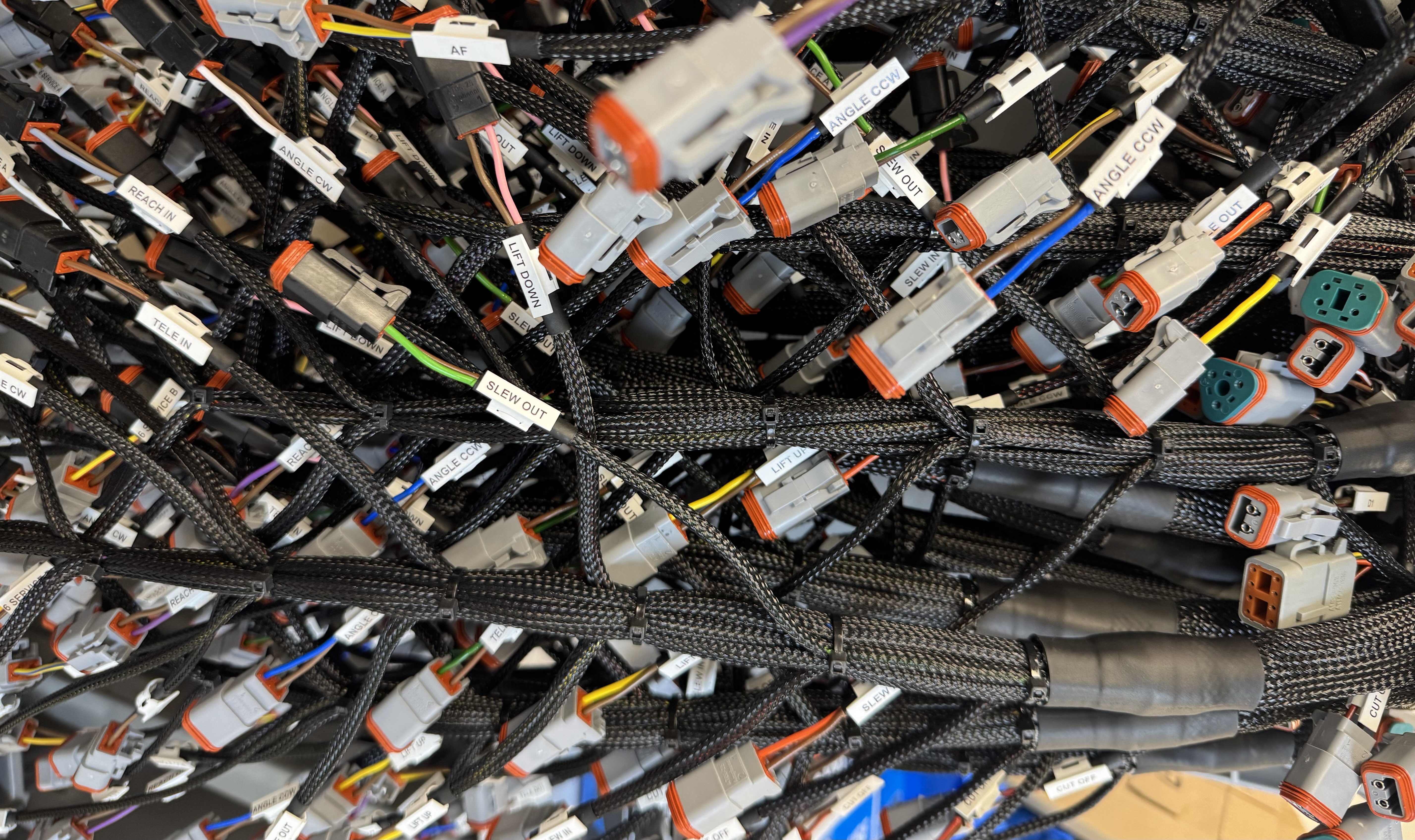
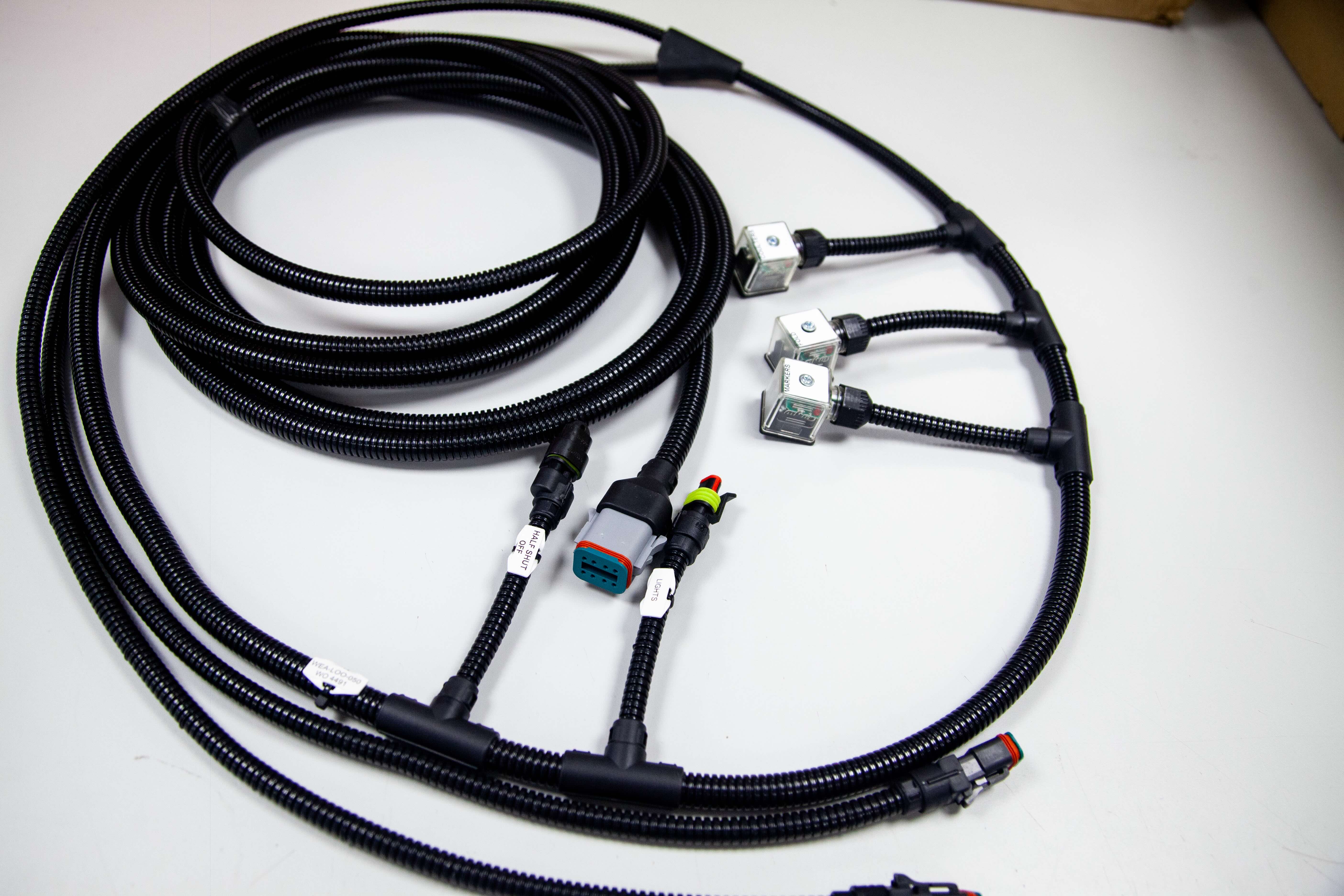
Typical elements include conductors sized by AWG and duty cycle, often tinned copper for corrosion resistance, with insulation selected for temperature and chemical exposure, for example PVC, XLPE, or PTFE. Connectors may be blade, ring, or sealed multi‑pin interfaces rated to IP67 or IP69K, with backshells and grommets for strain relief. Terminations are crimped or soldered, with ferrules on panel terminations to improve clamping integrity and reduce strand splay. Protective sheathing options include braided sleeving, split‑loom tubing, fabric wrap, and heat‑shrink boots, selected by abrasion class and routing constraints. Identification uses heat‑shrink markers, clear numbering, and color coding that align with panel documentation, which simplifies troubleshooting and accelerates change control. For deeper component scope, see this overview of harness elements and configurations Inside a Wiring Harness: Key Components & Configurations.
How electrical looms fit into modern manufacturing
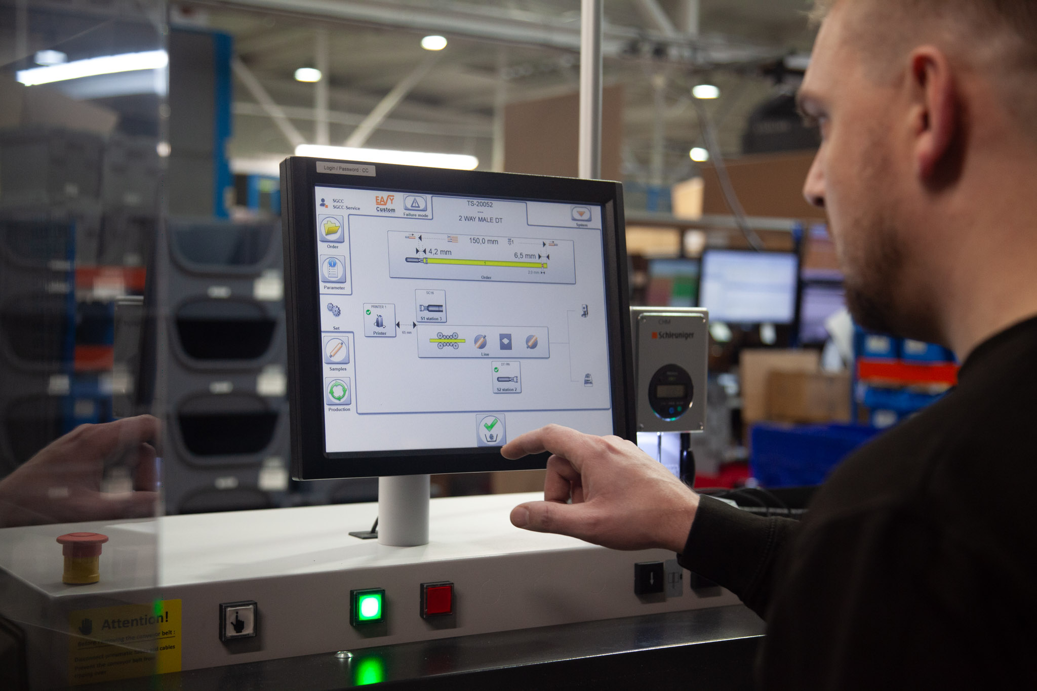
Electrical looms support lean assembly by enabling line‑side kitting, repeatable routing, and fast plug‑in verification. Automation in cutting, stripping, crimping, and labeling drives consistency and lowers labor cost, while inline continuity and hipot testing confirms build quality. Aerospace programs increasingly use smart test interfaces that auto‑generate test code, raising coverage and catching miswires early. Precision in routing, strain relief, and PCB integration maintains electrical performance and reduces rework, which aligns with ISO 9001:2015 quality objectives. With the wire harness market projected to grow at roughly 4.2 percent CAGR to 2034, OEMs benefit from standardized looms that scale reliably across product variants. For Tec‑Stop clients, this translates to dependable wiring solutions, predictable lead times, and confidence in every connection as we transition to detailed design and assembly practices in the next section.
Quality Assurance in Wiring Harness Production
Why quality assurance matters
Quality assurance is the foundation of dependable electrical loom assemblies, particularly where thermal cycling, vibration, and moisture are present. Robust QA translates design intent into repeatable outcomes by verifying conductor gauge, insulation type, terminal fit, and routing constraints against the print and bill of materials. Adherence to ISO 9001:2015 and IPC/WHMA-A-620 Class 2 or Class 3 workmanship criteria anchors documentation, training, and acceptance limits, and prevents ambiguity at the bench. Practical controls include calibrated pull-force checks per terminal datasheet, crimp height verification, 100 percent continuity and hipot testing for power looms, and visual inspection of ferrules, seals, and strain reliefs. These steps reduce rework and safety risk, and they build customer trust by ensuring harnesses leave production compliant and consistent. For a concise overview of QA benefits, see this summary on why quality assurance matters in wire harness manufacturing here.
MES for error tracking and traceability
A Manufacturing Execution System provides real-time visibility from cut-strip-crimp through final test. Barcoded travelers and work orders tie each loom to wire and terminal lots, operator ID, equipment ID, and in-process results such as crimp force, crimp height, strip length, and continuity outcomes. MES can interlock stations, only advancing work when critical checks pass, and log exceptions with photos to speed root cause analysis. Defects are timestamped and localized to a station and tool, enabling targeted containment and corrective action instead of broad quarantines. This level of genealogy supports rapid recall scoping, a key requirement for automotive and aerospace harnesses where liability and uptime matter.
SPC for proactive quality management
Statistical Process Control turns measurements into prevention. Track critical-to-quality characteristics such as crimp height and pull force using X-bar and R charts, and attribute data such as terminal backouts with p-charts. Establish control limits from an initial study, for example 25 subgroups of five pieces, then maintain action plans when points trend, drift, or exceed limits. Aim for Cpk of at least 1.33 on key dimensions, increase sampling frequency when special causes appear, and return to normal once stability is demonstrated. Feed SPC signals into the MES to automatically stop the line, alert maintenance, and verify corrective actions. Together, MES and SPC sustain quality at scale, giving OEMs confidence in every connection.
Innovations in Wiring Loom Technology
Sensor-enabled diagnostics inside the loom
Electrical looms are gaining embedded awareness through compact sensors and test interfaces that capture environmental and electrical context during build and operation. During validation, environmental modules now log temperature, humidity, and pressure alongside continuity and hipot results, simplifying chamber work and improving traceability. See examples of integrated environmental logging in harness testers in what’s new with harness testing technology. In service, adding IoT nodes at splice junctions or near high-current branches supports real-time thermal and voltage drop monitoring, which is valuable in connected vehicles and mobile equipment, as outlined in this overview of AI and IoT adoption in harnesses, Wiring the Future. Practical implementation tips: place thermistors within 5 to 10 mm of high-load terminations, sample at 1 to 5 Hz to balance power and fidelity, and set alert thresholds relative to conductor gauge and insulation rating. Tec-Stop ties these data points to lot records so OEMs can see exact environmental conditions for each assembly.
AI for better design, inspection, and compliance
AI is improving loom design, manufacturability, and inspection accuracy. Data-driven routing reduces crossings and bend stress, often cutting material usage by 3 to 8 percent while improving strain relief around connectors. Machine vision checks crimp height, wire brush length, and insulation strip length with high repeatability, and closes the loop to tooling presets. At the documentation level, rule-based verification maps drawing intent to terminal libraries and color codes, catching polarity or gauge mismatches before kitting. For a concise market view of AI’s role in harness manufacturing and the resulting productivity gains, see how AI, robotics, and automation are reshaping the market. To start, curate 500 to 1,000 labeled images per connector family, link nonconformance codes to camera results, and track yield by crimp tool ID.
Automated assembly and smart materials
Cut-strip-crimp cells, cobots for connector insertion, and automated labeling now deliver consistent quality with shorter takt times. Shops adopting semi-automated workcells routinely report 15 to 30 percent lead-time reductions and lower labor variance, aligning with industry-wide automation trends. Laser stripping and selective soldering add precision for fine-gauge or enamelled conductors in aerospace and medical micro-harnesses, reducing nicking risk. Smart material choices compound the gains: high-flex stranded conductors, fluoropolymer insulation for high temperature zones, lightweight shields, and abrasion-resistant braided sleeves extend service life without mass penalties. For actionable adoption, prioritize automation on families with stable demand and more than 10,000 terminations per month, qualify every new crimp barrel with pull-force and micrograph studies, and document routing rules that protect bend radius and strain relief. This approach keeps Tec-Stop wiring solutions consistent, serviceable, and ready for scalable production.
Effective Panel Wire Management Techniques
Device safety starts with disciplined panel wire management
In control panels, unmanaged conductors elevate thermal, electrical, and physical hazards. Dense, unbundled runs trap heat, accelerating insulation aging and raising the likelihood of shorts and fires, especially near high-load devices. Good routing, bundling, and strain relief reduce shock exposure by keeping live conductors shielded and stable, and by preventing abrasion at gland plates and terminations. Floor or door slack that escapes containment also creates trip hazards during service, a preventable risk with proper ducting and retention hardware. For a concise overview of heat, shock, and trip risk mitigation, see this guidance on long‑term electrical safety.
Best practices for efficient, serviceable organization
Plan the panel layout before a single conductor is cut. Define segregated wireways for power and control, target initial duct fill of 40 to 50 percent for future growth, and place high EMI sources, such as VFDs, away from sensitive I/O. Use color conventions, clear numbering, and ferrules to standardize terminations; print labels on both ends, matching the schematic net name to speed troubleshooting. Maintain manufacturer bend radius, often 8 to 10 times cable diameter for static runs, and add strain relief at the device and the cable entry to protect crimps and solder cups. Favor wire duct with fingers for fixed routing and reusable hook-and-loop ties in motion zones; reserve nylon ties with trimmed, flush heads for static bundles. Practical accessories and techniques are summarized in these effective cable and wire management tips.
Maintenance and operational impact
Organized panels shorten fault isolation because technicians can trace labeled conductors directly to their terminations without disturbing adjacent circuits. Neat routing improves airflow around heat sinks and power supplies, reducing localized hot spots and preserving component lifespan. Consistent labeling, documented color codes, and ferruled terminations align with ISO 9001:2015 practices, helping teams reproduce builds and audit changes reliably. Well-managed wireways also simplify upgrades, since spare capacity and clear segregation allow new runs to be added without rework. For Tec-Stop, disciplined management at the panel complements the electrical loom design, yielding wiring solutions and assemblies that stay reliable, maintainable, and ready for expansion.
The Future of Electrical Looms in Various Industries
Growth projections for the wire harness market
Market projections indicate sustained expansion for electrical looms across automotive, aerospace, medical devices, and industrial equipment. Independent analyses place the global wire harness market at USD 150.7 billion by 2030 with a 6.9 percent CAGR, and at USD 152.9 billion by 2035 with a 4.0 percent CAGR, reflecting differing end-market mixes and regional assumptions Wire Harness Market to Reach 150.7Bn by 2030, Market to Reach USD 152.9B by 2035. Long-range views near USD 146.3 billion by 2034 at a 4.2 percent CAGR corroborate steady, volume-driven demand. For OEM programs, this supports multi-year sourcing for terminals, seals, and jacket compounds, and early allocation of capacity for cut-strip-crimp and automated testing. Practical planning includes dual-qualifying critical components, validating alternates for wire types and connectors, and aligning harness release gates with platform PPAP timing.
Increasing demand fueled by eco-friendly vehicles
Eco-friendly vehicles are the clearest demand catalyst for complex electrical looms. EV and hybrid platforms increase harness content with high-voltage distribution, battery sensing, thermal management, and fast-charge interfaces. A U.S. Department of Energy loan closing of USD 362 million will fund a CelLink plant in Texas for flexible-circuit wiring, sized to support roughly 2.7 million EVs per year, underscoring the scale of upcoming production DOE loan to CelLink for EV wiring. Lightweight conductors and heat resistant jackets reduce vehicle mass while maintaining creepage and clearance in 400 to 800 volt architectures. Actionable steps include locking high-voltage color conventions, shield termination methods, and service loop policies early, and running DFMEA on charge, traction, and thermal sub-assemblies to de-risk EMC and serviceability.
Adapting to future technological advancements in loom production
Loom production is shifting to smart, automated assembly to improve reliability and throughput. Smart manufacturing is raising first pass yield through automated routing, in-line continuity and hipot, and digital travelers tied to component barcodes Smart manufacturing integration outlook. Data-dense applications, including ADAS and aerospace avionics, require controlled-impedance cable sets, documented bend radii, and robust strain relief. Teams should standardize on ISO 9001:2015 aligned process controls, automated test code generation, and revision-controlled fixture libraries. For practical readiness, run design for manufacturability checks on routing and clamp spacing, specify ferrules, labeling, and numbering per control panel best practices, and pilot automated build-offs to verify repeatability before releasing to volume.
Practical Steps in Creating Durable Electrical Looms
Select materials and tools that sustain service conditions
Start with wire types that match current, temperature, and flexibility requirements. For automotive and industrial looms, cross-linked polyethylene insulation such as TXL or XLPE typically supports 125 C ratings, while PTFE options can operate near 200 C for high heat zones. Protective sleeving should be chosen by environment, for example split Nomex sleeves that tolerate roughly -76 F to 392 F for fire resistance, or self-closing split sleeves tested to about 302 F where abrasion dominates. Use sealed connectors and terminals with appropriate IP ratings, such as IP67 in splash or dust environments, and verify crimps with terminals that match conductor stranding and gauge. Equip the bench with calibrated cut-strip-crimp machines or ratcheting crimpers, matched dies, heat guns for adhesive-lined heat shrink, cable tie tools with tension control, and a multimeter or automated continuity tester. As a quick sizing rule, target less than 2 percent voltage drop on power runs, and segregate low-level signals from high-current conductors to reduce noise.
Assemble the loom with a disciplined, test-first process
Begin with a schematic and a harness board that fixes branches, connector keys, and lengths, leaving 5 to 10 percent service loop where maintenance access is required. Cut and strip conductors to print, apply wire ferrules for panel terminations, and mark each end with clear numbering aligned to your drawing set to speed installation and service. Group wires by function, then sleeve and branch with transitions reinforced by adhesive-lined heat shrink; maintain a minimum bend radius of 10 times the bundle diameter. Bundle using cable ties at roughly 150 mm intervals, but avoid over tightening by using a tensioning tool and flush cutters to prevent sharp edges. Crimp with verified pull-force, add strain relief boots at connectors, then conduct 100 percent continuity and short testing, ideally on an automated tester that logs results. During installation, route away from hot surfaces by at least 75 mm unless protected, separate power and signal by 50 mm where practical, and cross at 90 degrees to minimize coupling.
Where Tec-Stop adds value to your loom program
Tec-Stop delivers wiring solutions and assemblies built on repeatable process control, first-article validation, and clear documentation from drawing through shipment. We use cut-strip-crimp automation and fixture-based builds to improve consistency, then perform 100 percent continuity testing in line with ISO 9001:2015 quality practices. For control panel wiring, we standardize ferrules, numbering, and color coding to enhance safety and traceability. Our team communicates early on routing, strain relief, and connector selection so OEMs receive dependable, installation-ready looms. The result is a precise, durable electrical loom that integrates cleanly into your equipment and supports reliable field performance.
Conclusion: Ensuring Quality and Precision in Wiring Loom Assemblies
Recap and execution priorities
Mastering an electrical loom begins with translating electrical requirements into a routable, serviceable bundle that respects space, heat, and motion. Define conductor size and insulation to match current and environment, for example, cross-linked polyolefin for 125 C engine bays or flexible PVC for indoor panels. Lock in routing early, target bend radii of at least 8 times the outer diameter for static runs and 10 times for dynamic flex, and plan clamp spacing around 150 to 200 mm with strain relief at branch exits. Protect contact interfaces with ferrules, specify blade widths and terminal series explicitly, and document crimp height and bellmouth targets so first-article builds can be verified. Apply disciplined identification, clear numbering, and color coding that aligns with your control panel schema to simplify commissioning and troubleshooting. Where harnesses mate to PCBs, involve layout early to optimize connector orientation, keying, and keep-out zones, which reduces assembly time and rework.
Commit to QA, innovation, and partnerships
Quality assurance sustains reliability as volumes scale. Anchor your process to ISO 9001:2015 quality management, use first-article approvals, 100 percent continuity testing with hipot where appropriate, validated pull-force testing to connector specifications, and barcode traceability through each build stage. Adopt modern techniques that reduce variability and cycle time, such as automated cut, strip, and terminate lines, digital work instructions with in-process checks, and smart test interfaces that auto-generate test code to match the loom’s netlist, an approach proven in aerospace programs. As wires and insulation compounds become more adaptable and reliable, and as automation improves throughput, you gain repeatability and faster turnarounds. Market demand supports these investments, with the wire harness sector projected to reach about 146.3 billion USD by 2034 at a 4.2 percent CAGR, and strong growth in automotive assemblies. Partnering resourcefully amplifies results. Tec-Stop delivers precise wiring solutions and control panel assemblies with DFMA reviews, tooling selection, automated test development, and steady communication, helping OEM teams implement these methods without friction. Carry these practices into your next build, and you will ship looms that are durable, verifiable, and ready for production with confidence in every connection.