Voltage drop, nuisance lockouts, and melted connectors usually trace back to one thing, poor wiring. If you are installing or refreshing an Espar Airtronic D2, getting the espar d2 wiring right is the difference between a reliable heater and long nights of troubleshooting. This guide targets intermediate DIYers and technicians who can read a schematic and crimp a terminal, and want a precise, step-by-step process.
You will learn how to plan the circuit, select the correct AWG based on run length and current, and size fuses for protection and serviceability. We will map each harness lead to its function, power, ground, pump, controller, and diagnostics, then show clean routing practices that minimize EMI and chafing in vans, RVs, and marine compartments. You will see proper grounding strategies, relay use for ignition-sense, and best practices for splices, strain relief, and heat-shrink sealing. Finally, we will walk through commissioning, voltage checks under load, priming the pump, verifying polarity, and interpreting common fault codes. By the end, you will have a repeatable wiring workflow that prevents most heater issues and simplifies future servicing.
Understanding the Basics of Espar D2 Wiring
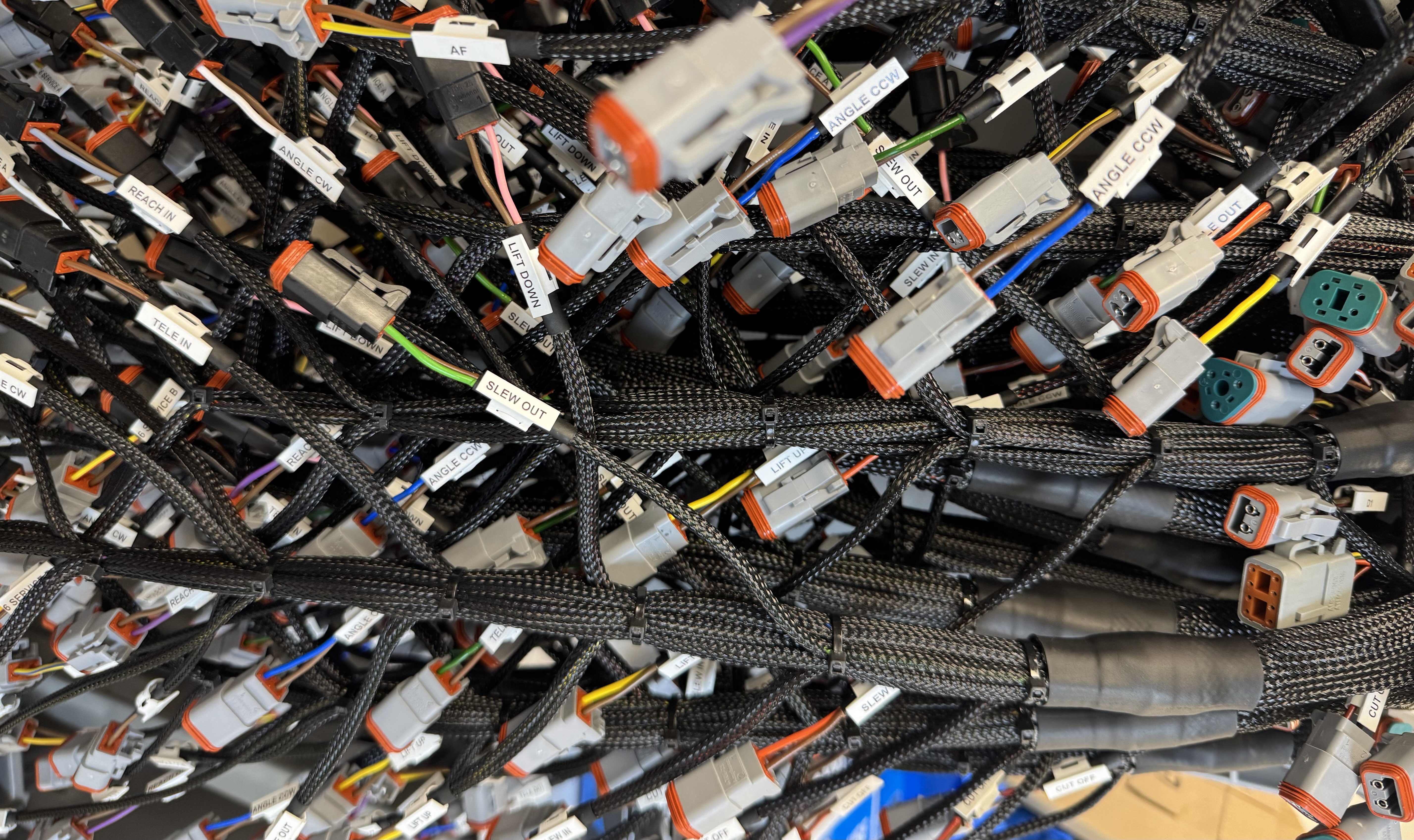
The Airtronic D2 is a compact diesel air heater with a straightforward architecture that rewards careful wiring. Core components include the heater unit, an integrated control board, the fuel metering pump, the blower, the thermostat or controller, and the main wiring harness. The heater draws cabin air across a heat exchanger while the control board modulates the pump to meter fuel precisely. In common looms brown is the negative return, so all brown conductors should tie to the same ground reference to prevent floating faults. Many installers note a controller with 6 conductors mated to a harness with 7 conductors; the extra position is often for diagnostics or model options and must be managed according to the harness pinout. Plan the power feed for a 25 amp maximum current, which typically means 10 to 12 AWG supply conductors over short runs to keep voltage drop within spec.
Wiring quality and model specifics
Most misfires and lockouts trace back to voltage drop, loose terminations, or incompatible harnesses. Use high strand-count copper, sealed terminals, proper strain relief, and route signal and pump conductors away from ignition noise. Model variants such as D2L and later generations may require adapter harnesses when interfacing with earlier looms; confirm connector keys and pin assignments before energizing. For example, the S2-D2L replacement references specific adapter harnesses to mate to existing main looms, a reminder that pin-for-pin swaps are not guaranteed; review the notes on the Espar Airtronic S2-D2L replacement details. If you prefer a visual walkthrough, this detailed S2D2 installation tutorial highlights controller wiring, pump polarity, and fuse placement. Tec-Stop specifies quality conductors and interconnects to reduce resistance and improve durability; see our cables, wires, and components used in dependable assemblies.
Quick wiring checklist
Prerequisites and materials: verified model and harness generation, accurate pinout, 10 to 12 AWG supply conductors, sealed crimps, proper fuse or breaker rated to protect a 25 amp circuit, and a reliable chassis ground point.
Plan the routing, separating power, signal, and fuel lines to minimize interference.
Terminate the supply with sealed crimps, then install overcurrent protection as close to the source as practical.
Bond all brown returns to a clean, low-impedance ground.
Confirm controller-to-harness pin mapping when a 6-wire controller meets a 7-position loom.
Perform a cold resistance and continuity check, then power up and verify pump pulsing and blower start.
Expected outcome: stable start-up, consistent combustion, and reduced error codes from clean, low-drop espar d2 wiring.
Gathering Prerequisites and Materials
Tools, test equipment, and PPE
Reliable espar d2 wiring starts with a clean bench, verified tools, and PPE. Stock a multimeter, ratcheting crimper, heat gun, wire strippers, cable shears, a drill with hole saws, and a deburring tool. Keep a terminal removal tool or diagnostic handset ready for pin checks, see the concise list in the installation FAQs. PPE should include cut resistant gloves, safety glasses, hearing protection, and a respirator. Step 1, inventory and function check tools; Step 2, stage heat shrink, tinned lugs, and loom; Step 3, clear a well lit area for harness layout.
Wiring specifications and materials
The D2 supply can draw up to 25 amps at ignition, so fit a 25 amp fuse near the battery and size conductors to limit voltage drop. Up to 4 meters round trip use 4 mm² about 12 AWG; 4 to 6 meters use 6 mm² about 10 AWG; 6 to 10 meters use 10 mm² about 8 AWG per this technical reference. Brown is the negative return, tie all brown leads to a common negative bus and keep color discipline. Use tinned copper cable, adhesive lined heat shrink, abrasion resistant loom, and grommets at every pass through.
Components and sourcing
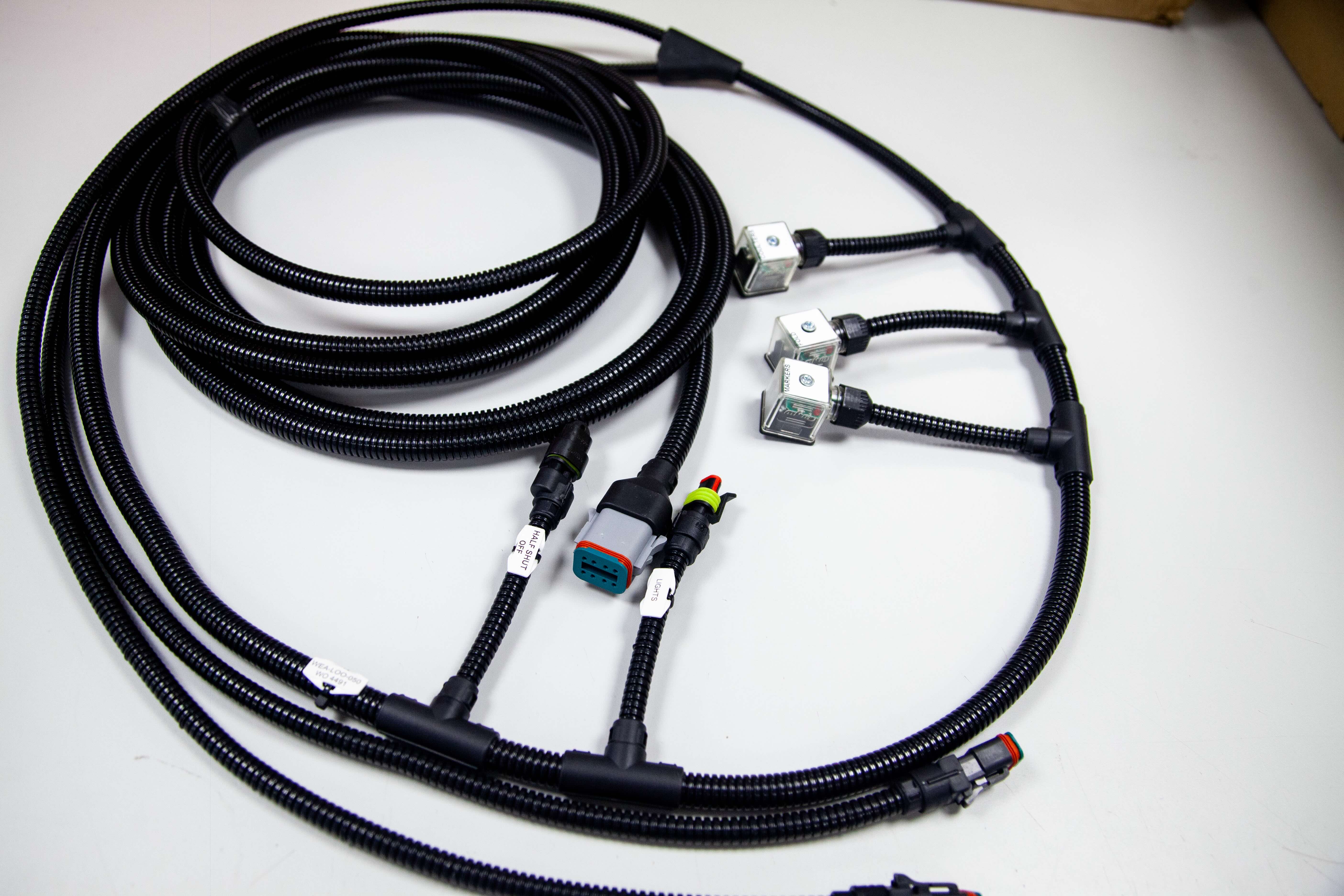
Stage the heater, model specific harness, metering pump, exhaust and intake tubing, control head, and mounting hardware. If mixing D2, D2L, or D4L generations, confirm connector compatibility or use an adapter, see D2 and D4 wiring harness. The controller may have six conductors while the harness shows seven, verify pinouts and cap unused leads. Add cable glands, P clamps, adhesive tie mounts, and heat shrink for connector strain relief. Source pre terminated wiring solutions and assemblies from Tec-Stop, then label conductors for drop in installation. The outcome is a complete, labeled kit ready for efficient installation.
Step-by-Step Wiring Instructions
Prerequisites, placement, and securing
Materials: 10 to 12 AWG supply cable rated for 90 C, 20 A fuse for 12 V or 10 A for 24 V per model guidance, OEM heater harness, heat‑shrink butt splices, braided loom, rubber grommets, P‑clips or cable ties, multimeter. 1) Mount the heater first, then seat the main 16‑pin harness plug until latched. 2) Route the harness along factory looms on the cool side of the bay, maintaining at least 100 mm clearance from exhaust components and 25 mm from moving parts. 3) Add abrasion protection with braided loom through bulkheads and grommet all pass‑throughs. 4) Secure every 150 to 200 mm with P‑clips or cable ties, leaving 10 to 15 mm of service loop at connectors for strain relief. 5) Terminate the supply at the battery with ring lugs, planning for up to 25 A inrush, so size conductors accordingly.
Critical leads, red/grey and brown/white
Identify the red/grey and brown/white pair in the heater harness. 2) For internal temperature sensing, join red/grey to brown/white, insulate with heat‑shrink, and label the splice. 3) If using an external sensor, land the sensor brown/white to the joined red/grey and brown/white, and the sensor grey to the harness grey; this resolves the common no‑temperature display fault described here, see temperature sensor wiring guidance. 4) Remember that brown is negative throughout the assembly, bond all browns to a single ground point.
Control unit, components, and validation
Power, red to battery positive through the fuse located within 200 mm of the source, brown to battery negative or a clean chassis stud with less than 0.1 ohm back to battery. 2) Route the 7‑core switch harness to the controller; many thermostats present 6 conductors, so cap any unused lead per the controller manual and confirm heater generation before mating. 3) Connect fuel metering pump two‑core lead, polarity is non critical, protect the run in loom. 4) Continuity test every splice and conductor, then key‑on and confirm controller wake, pump tick at startup, and blower ramp without error. 5) Verify voltage drop under 0.5 V on the supply during ignition. For additional layout context, see this practical walkthrough, Espar D2 diesel heater installation notes.
At Tec‑Stop, we keep espar d2 wiring quiet and stable by separating heater looms from high current alternator or starter cables by 150 mm, using star‑ground practice, crimped ferrules in terminal blocks, and consistent strain relief to eliminate buzz, nuisance resets, and EMI.
Tips for Optimal Installation and Maintenance
Placement clearances and access
Plan the mounting so airflow is unobstructed and service tasks are straightforward. Maintain at least 2 inches of space around the cabin air intake and keep the intake away from heat sensitive materials to reduce fire risk and recirculation of hot air, per the Airtronic guidance in installation clearances. Separate the combustion intake and exhaust terminations to prevent cross contamination and avoid placing the intake where road spray or debris accumulates. Leave a direct, tool friendly path to remove the glow pin and screen without dismounting the heater. Provide cable service loops so connectors can be unplugged and tested in situ. Expected outcome: stable airflow, safe routing, and quick maintenance access.
Verify 2 inch minimum clearance at the intake with a feeler gauge or ruler. 2) Dry fit the cover and confirm a straight extraction path for the glow pin. 3) Add abrasion sleeves and edge grommets anywhere the harness passes through metal.
Routine checks and glow pin service
Set a quarterly checklist that focuses on voltage, fuel, and airflow. Under load, the unit must see at least 10.5 V; low voltage causes no start or flame out events documented in the service bulletin. Confirm the brown conductors are tied to the negative bus throughout the assembly, then verify the supply path can carry up to 25 A with 10 to 12 AWG conductors and tight, corrosion free crimps. Inspect the metering line for bubbles, confirm the tank has clean diesel, and clear intake or exhaust obstructions that trigger overheat shutdowns. Expected outcome: reliable starts and stable burn. 4) Measure battery voltage at the heater while it is starting. 5) Check fuel level and filter. 6) For glow pin service, disconnect power, unplug the lead, remove the pin with a dedicated glow pin removal tool, clean carbon from the pin and screen, then replace the screen if fouled.
Altitude and Tec-Stop wiring ethos
Altitude compensation mitigates mixture changes, but long operation above roughly 1,500 meters benefits from periodic high power runs to prevent carbon buildup. After any high altitude trip, schedule a brief inspection of the screen and intake path. For wiring reliability, avoid mixing harness generations, label the 6 conductor controller lead and the 7 conductor main harness clearly, and continuity test every run before power up. Bundle all browns to the negative bus, apply strain relief at the heater and controller, and keep diagnostic access points reachable. At Tec-Stop we prioritize clean, labeled assemblies, consistent crimps, and documented test results, giving OEMs confidence in every connection.
Troubleshooting Common Wiring Issues
Prerequisites and expected outcomes
Before troubleshooting espar d2 wiring, prepare a calibrated multimeter, test leads with piercing probes, dielectric grease, contact cleaner, heat‑shrink, crimp splices, and a 12 V load lamp. Confirm the supply run uses 10 to 12 AWG with secure terminations since the heater can see up to 25 A during startup, per the Airtronic D2 specifications. Verify the correct model harness is installed because D2, D2L, and later revisions use different connectors and pinouts. The expected outcome of this procedure is a repeatable start cycle without error codes and stable operation through full heat output. Document voltages, continuity results, and any corrected joints to support future service.
Recognize typical wiring faults
Look first for power issues, such as voltage drop under crank or glow, that show up as no start, short cycling, or controller resets. Corroded or loose spade and multi-pin connectors often cause intermittent shutdowns, especially in damp compartments, and will leave light oxide on the pins. The brown wire is the negative return throughout the assembly, so all browns should land on a clean common ground to avoid floating references. Harness confusion is common because many thermostats present 6 conductors while the main harness shows 7; the extra lead is unused on some controllers and must be capped and insulated if not populated. Physical abrasion of the loom, especially where it passes through bulkheads, can create shorts that trip fuses or trigger fault codes.
Address power, harness, and connectivity
Step 1, measure battery-to-heater positive with the heater commanded on and glow active, and target minimal drop relative to battery. Step 2, inspect every connector, clean with contact cleaner, re-seat until positive engagement, then apply dielectric grease sparingly at the seal. Step 3, perform continuity and polarity checks from the controller plug through the main harness to the heater, confirming the brown negative is common at every junction. Step 4, repair nicks using heat‑shrink butt splices and strain relief, then reroute away from sharp edges and fuel lines. Step 5, confirm the supply fuse rating and holder condition, and verify wire gauge meets the 10 to 12 AWG recommendation for the 25 A inrush.
Verify glow pin and temperature sensor
Step 1, isolate power and allow the heater to cool fully. Step 2, remove the glow pin, inspect for carbon fouling or cracked ceramic, clean lightly if serviceable, and measure resistance, then compare to the specification in the technical manual. Step 3, bench test the glow pin by applying limited current through a fused lead to confirm uniform heating if resistance is within spec. Step 4, disconnect the temperature sensor and record resistance at ambient, then gently warm it and confirm smooth resistance change without jumps. Step 5, replace components that deviate from published values, and clear any stored lockouts before retest.
Optimize control unit checks using Tec-Stop guidelines
Use a structured sequence to reduce retries and lockouts. Start with a cold boot, command heat, then log the exact point of failure, for example preheat, blower ramp, or pump trigger, to pinpoint which circuit is suspect. Read fault codes on the controller or with a compatible diagnostic interface, correct the physical cause, and clear codes only after verification. Apply Tec-Stop practices, including labeled harness mapping, measured voltage logs at each pin, and a pass-fail checklist for grounds, supplies, control lines, and sensor circuits. Finish with a full run at maximum output and a cool-down cycle to confirm the assembly is dependable and ready for service.
Final Checks and Professional Assurance
Post‑installation functional checks
Prerequisites: completed wiring, multimeter, clamp meter, inspection mirror, and access to the controller. Materials: spare fuses, dielectric grease, cable ties, and an infrared thermometer. Expected outcome: clean startup, stable operation, and no fault codes. 1) Verify supply capacity: confirm 10 to 12 AWG feed and a correctly sized fuse, then measure voltage at the heater connector during start. Keep drop under 10 percent at peak draw, the assembly should be sized for up to 25 amps. 2) Confirm polarity: brown is negative throughout, tie all brown returns to a solid ground or return bus. 3) Inspect controller lead count: many controllers present 6 wires while the harness shows 7. Identify the extra harness lead and cap it if unused on your controller and model. 4) Prime and inspect fuel, check for clear fuel line with no bubbles and tight crimps at the metering pump. 5) Check intake and exhaust routing, no obstructions and correct clearances, with clamps fully seated. 6) Perform a cold start, observe current with a clamp meter through warmup and modulation, then perform a controlled shutdown. 7) Log readings and any codes for future reference.
Securing connections for long‑term reliability
Prerequisites: light source, mirror, tie mounts, protective loom, adhesive‑lined heat‑shrink, and a ratcheting crimper. Route harnesses away from heat and abrasion, maintain gentle bend radius, and use grommets at every panel pass‑through. Apply strain relief, add tie points every 150 to 200 mm, and bundle service loops where access is needed. Perform a crimp pull test on every joint, then seal with adhesive‑lined heat‑shrink. Protect exposed terminations with dielectric grease. Torque battery and chassis lugs per fastener specs and label both ends of every lead for future service.
Precision, inspections, and professional assurance
Consistent practices reduce callbacks. Use model‑specific harnesses and verify connector keying when working across generations, for example D2L versus earlier D2 variants. Maintain a wiring map that notes controller wire count, unused leads, fuse ratings, and measured voltage drop. Schedule seasonal inspections: recheck torque on lugs, inspect for chafe, confirm brown return continuity, and retest startup behavior. Tec‑Stop provides dependable wiring solutions and assemblies, including labeled harnesses, protection hardware, and clear documentation, along with technical support for inspection routines and upkeep. This disciplined approach delivers reliable espar d2 wiring and confidence in every connection.
Conclusion and Actionable Takeaways
For espar d2 wiring, follow this sequence: 1) size the supply with 10 to 12 AWG, verify the path can deliver up to 25 A, and fit the model-correct fuse, 2) tie all brown conductors to a single negative point, 3) confirm the harness and controller are model compatible, 4) ring out the controller lead set, thermostat shows 6 wires, harness 7, isolate the extra lead. Keep current runs short and target less than 3 percent voltage drop. Use crimped, strain relieved terminations with heat shrink, then continuity check each circuit before power up. Complete a dry run and glow cycle with a clamp meter to confirm no overcurrent events.
Establish regular checks, monthly in heavy use or quarterly, target start voltage above 11.5 V on 12 V builds and less than 0.5 V drop during glow. Inspect grounds, clean, re-torque battery studs, verify connector latches, and log starts, lockouts, and hours to catch trends early. Person oriented wiring means clear labels at both ends, service loops the next technician can grab with gloves, and cable paths that make access intuitive. Tec-Stop backs dependable builds with pre-verified wiring solutions, labeled control panel assemblies, and checklists that keep installations smooth, helping capture 1 to 2 thousand dollars in DIY savings while maintaining reliability.